2026-05-13
An Arduino segment display is a versatile output component used to visualize numerical data and simple characters in embedded projects. By controlling individual LED segments through digital pins or shift registers, makers can create clocks, counters, and status indicators. This guide provides a comprehensive walkthrough on wiring, coding libraries, and expert optimization techniques to ensure your display functions reliably with minimal resource usage.
A segment display, specifically the 7-segment variety, consists of seven LED elements arranged in a figure-eight pattern plus an optional decimal point. When interfaced with an Arduino board, these segments light up in specific combinations to form digits from 0 to 9 and some letters. Understanding the internal configuration is critical for successful implementation.
There are two primary electrical configurations: Common Cathode and Common Anode. In a common cathode setup, all negative terminals connect to ground, requiring a HIGH signal to illuminate a segment. Conversely, common anode displays share a positive connection to VCC, needing a LOW signal to activate segments. Selecting the correct type dictates your wiring strategy and code logic.
These components remain industry staples due to their high brightness, readability from a distance, and low power consumption compared to graphical LCDs. They are ideal for applications where displaying raw numeric data is the primary objective without the overhead of complex graphics processing.
Before writing code, establishing a robust physical connection is paramount. Directly connecting a multi-digit display to an Arduino Uno can quickly exhaust available GPIO pins. Therefore, understanding pin mapping and current limiting is essential for a stable circuit.
Each segment requires a current-limiting resistor, typically between 220Ω and 330Ω, to prevent LED burnout. Without these resistors, the voltage drop across the LEDs may cause excessive current flow, damaging both the display and the microcontroller. Always consult the datasheet for the specific forward voltage of your unit.
For single-digit projects, direct wiring is feasible but inefficient for larger setups. Connecting four digits directly consumes nearly 32 pins when including decimal points, which is unsustainable for standard boards. Industry professionals predominantly use driver ICs like the TM1637 or MAX7219 to manage multiplexing internally.
Using a driver module significantly reduces wiring complexity. These chips handle the rapid switching required for multiplexing, ensuring consistent brightness without flickering. This approach frees up microcontroller pins for sensors, buttons, or communication modules, enhancing overall project scalability.
Programming an Arduino segment display involves defining pin states corresponding to specific numbers. While manual bit-mapping offers educational value, leveraging established libraries ensures reliability and saves development time. The following steps outline the process using a popular 4-digit module.
First, install the necessary library via the Arduino IDE Library Manager. Search for “TM1637” or the specific driver compatible with your hardware. Once installed, include the header file in your sketch to access pre-built functions for brightness control and digit rendering.
Initialize the display object by specifying the clock and data pins. Set the initial brightness level to avoid overwhelming glare in dark environments. The library handles the timing-critical multiplexing automatically, allowing the main loop to focus on application logic.
To show a number, use the dedicated display function. For dynamic content, such as a counter or sensor reading, convert the integer to a string or pass the value directly depending on the library’s API. Always clear the display before updating to prevent ghosting artifacts.
Beyond basic numbers, advanced users can manipulate individual segments to create custom symbols or animations. By accessing the low-level byte mapping, you can light specific segments to represent units like “C” for Celsius or “F” for Fahrenheit. This requires understanding the hexadecimal representation of segment patterns.
Implementing non-blocking code is crucial for responsive projects. Avoid using delay() functions for blinking effects or counting loops. Instead, utilize the millis() timer to manage display updates independently from sensor readings, ensuring smooth operation even during intensive data processing.
Even with careful planning, issues like dim lighting, flickering, or incorrect digits may arise. Diagnosing these problems systematically saves hours of frustration. Most errors stem from power supply limitations, incorrect pin definitions, or logic mismatches between common anode/cathode types.
If the display appears dim, check the power source. USB ports may not provide sufficient current for multiple bright LEDs. Using an external 5V power supply with a common ground often resolves brightness inconsistencies. Additionally, verify that current-limiting resistors match the recommended values for your specific LED forward voltage.
Flickering usually indicates a timing issue in the multiplexing refresh rate. If writing custom code without a library, ensure the refresh frequency exceeds 60Hz to leverage human persistence of vision. When using libraries, check for conflicting interrupts or heavy processing loads in the main loop that starve the display update routine.
Ghosting occurs when segments faintly light up when they should be off. This is often caused by floating pins or improper transistor switching in multiplexed circuits. Ensure all unused pins are defined as outputs or pulled down/up appropriately. Adding small capacitors near the power input of the display module can also stabilize voltage fluctuations.
| Issue | Potential Cause | Solution |
|---|---|---|
| Dim Display | Insufficient Current | Use external 5V power supply; check resistor values. |
| Flickering | Low Refresh Rate | Increase multiplexing frequency; optimize loop code. |
| Wrong Digits | Pin Mapping Error | Verify CLK/DIO connections; check library configuration. |
| Ghosting | Floating Pins | Set unused pins to OUTPUT; add decoupling capacitors. |
Efficient resource management distinguishes amateur prototypes from professional products. An optimized Arduino segment display project minimizes CPU load and power consumption, extending battery life in portable applications. Strategic coding practices and hardware choices play a pivotal role here.
Reducing the brightness dynamically based on ambient light is a sophisticated technique. Integrating a photoresistor allows the system to lower LED intensity in dark rooms and boost it in sunlight. This not only saves power but also improves user comfort by preventing eye strain.
Storing segment maps in program memory (PROGMEM) rather than RAM conserves valuable volatile memory on smaller boards like the Arduino Nano. This is particularly important when combining displays with other memory-intensive libraries such as WiFi or Bluetooth stacks.
Avoid redundant calculations within the main loop. Pre-calculate segment patterns for static characters and store them in arrays. Only perform mathematical conversions for changing values. This reduces the cycle count per iteration, allowing the microcontroller to enter sleep modes more frequently if battery operation is a priority.
The versatility of segment displays makes them suitable for a wide array of practical applications. From industrial monitoring to consumer electronics, their ability to present clear, high-contrast data ensures continued relevance in the IoT era.
In home automation, these displays serve as intuitive interfaces for thermostats, smart clocks, and energy monitors. Their simplicity allows users to glance at critical information instantly without navigating complex menus. For industrial settings, they provide rugged status readouts for machinery parameters like temperature, pressure, or cycle counts.
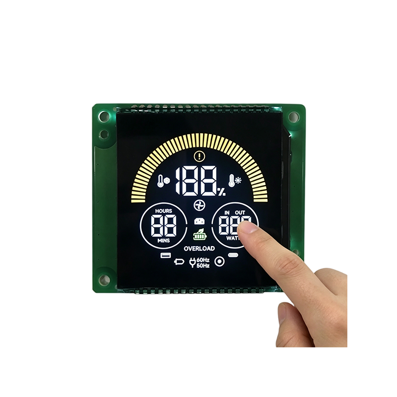
While hobbyists often prototype with off-the-shelf modules, large-scale deployments in sectors like automotive electronics, medical equipment, and industrial instrumentation frequently require tailored solutions. This is where specialized manufacturers like Dalian Eastern Display Co., Ltd. play a crucial role. With factories in Dalian and Dongguan equipped with professional production technology, the company specializes in designing and producing customized LCD screens and modules. Having delivered over 10,000 unique products ranging from segment codes and character dot matrices to graphic dot matrix LCDs and TFT displays, they serve as a qualified supplier for many well-known manufacturers. Their massive annual capacity—50,000 square meters of LCD screens and 10 million display modules—ensures that whether you need a standard component or a fully custom OEM/ODM solution for home appliances or precision instruments, reliable mass production is achievable.
Makers frequently employ segment displays in countdown timers, scoreboards, and retro-style gaming consoles. The nostalgic aesthetic combined with modern microcontroller capabilities creates engaging interactive experiences. Educational kits often use them to teach binary counting and decimal conversion concepts.
Portable devices benefit greatly from the low power profile of modern LED segments. Battery-operated multimeters, handheld tachometers, and field measurement tools rely on this technology for reliable visibility in various lighting conditions. The robustness of the components ensures longevity even in rough handling scenarios.
While OLED and LCD screens offer graphical capabilities, segment displays hold distinct advantages in specific niches. Choosing the right output method depends on the project’s requirements for readability, power, and complexity. A comparative look highlights where segment displays excel.
Graphical displays require significant processing power to render pixels and often consume more energy. In contrast, segment displays dedicate all emitted light to useful information, resulting in superior visibility under direct sunlight. They are also generally more cost-effective for applications requiring only numeric output.
| Feature | Segment Display | OLED/LCD Screen |
|---|---|---|
| Readability (Sunlight) | Excellent | Poor to Moderate |
| Power Consumption | Low (Static images) | Higher (Pixel driving) |
| Code Complexity | Low | High |
| Cost | Very Low | Moderate to High |
| Data Type | Numeric/Simple Alpha | Graphics/Text/Video |
Addressing common queries helps clarify uncertainties regarding compatibility, coding, and hardware selection. These answers reflect current industry standards and practical experiences from the maker community.
Yes, you can chain multiple displays, especially when using driver ICs like the TM1637 or MAX7219. These chips support daisy-chaining, allowing you to control several units using just two or three GPIO pins. Ensure your power supply can handle the cumulative current draw of all active LEDs.
Random characters often result from uninitialized variables or noise on the data lines. Check your wiring for loose connections and ensure you have stable grounding. Adding a small capacitor between VCC and GND near the display module can filter out electrical noise causing erratic behavior.
Ideally, yes. Individual resistors ensure consistent brightness across all segments and protect against varying forward voltages. While some modules have built-in resistors, discrete builds require external components to prevent thermal runaway and extend the lifespan of the LEDs.
Not all letters can be accurately represented due to the limited segment count. However, characters like A, b, C, d, E, F, H, L, P, and U are commonly achievable. You must define custom byte maps for these characters, treating the display as a grid of 8 bits (including the decimal point).
Achieving a polished finish involves attention to details often overlooked in beginner tutorials. Professional-grade implementations prioritize reliability, maintainability, and user experience. Incorporating these expert tips will elevate your project quality.
Always design your PCB or breadboard layout with serviceability in mind. Leave test points for voltage measurements and ensure connectors are accessible. Document your pin mappings clearly in the code comments to facilitate future modifications or troubleshooting by others.
Mastering the Arduino segment display opens doors to creating clear, efficient, and professional embedded systems. By understanding the nuances of common anode/cathode configurations, utilizing driver ICs, and optimizing code for performance, you can build robust projects that stand the test of time.
This technology is best suited for engineers and hobbyists focusing on data visualization where clarity and low power are paramount. Whether building a kitchen timer, an industrial counter, or a custom instrument panel, the principles outlined here provide a solid foundation. For those looking to scale from a single prototype to mass production, partnering with experienced manufacturers ensures consistency and quality across thousands of units.
To advance your skills, consider experimenting with different driver chips or integrating wireless modules to transmit data remotely to your display. Start by prototyping a simple counter, then gradually incorporate sensor inputs and adaptive brightness features to create a fully functional, user-friendly device.